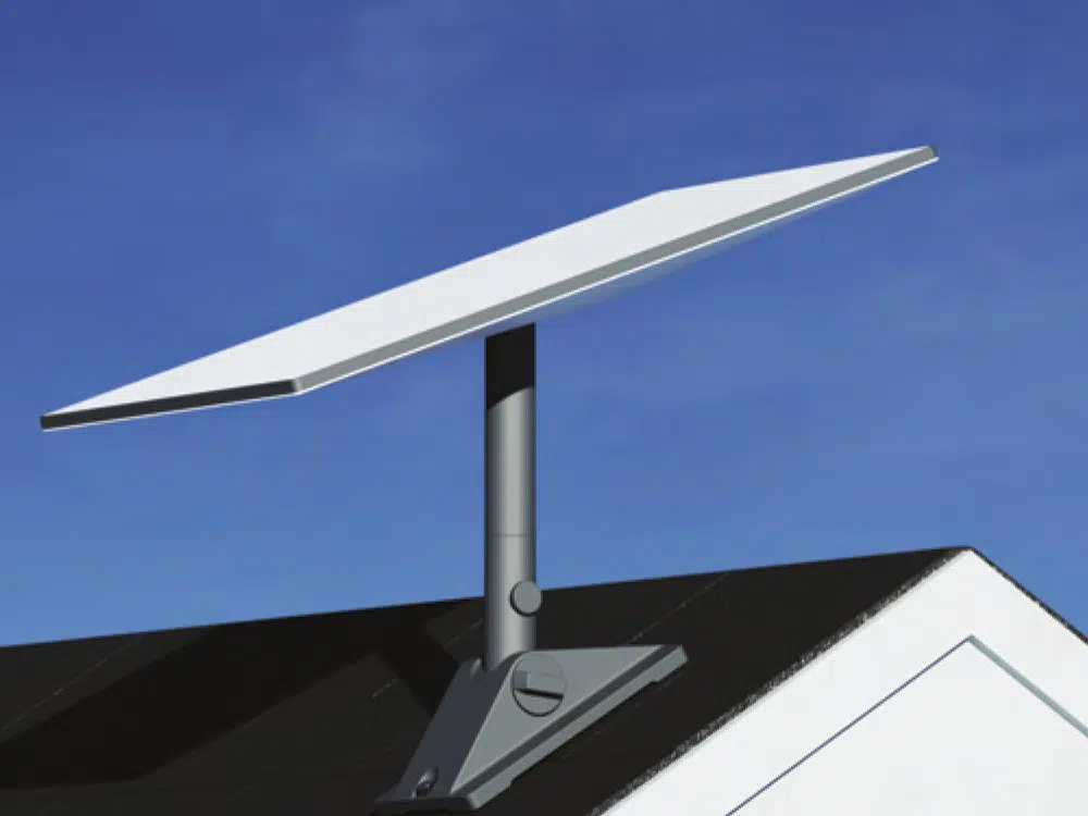
Low Earth Orbit (LEO) satellite technology has revolutionised maritime connectivity. Commercial vessel operators, offshore wind support fleets, and workboat crews can now access high-speed, low-latency broadband far beyond the reach of terrestrial mobile networks.
However, achieving enterprise-grade reliability at sea requires more than mounting a standard consumer dish to a vessel mast. Deploying a commercial Starlink antenna in harsh marine environments introduces specific engineering challenges—including structural vibration, salt fog exposure, thermal stress, and signal occlusion caused by ship superstructures, cranes, and exhaust stacks.
For marine engineering teams and vessel superintendents, specifying the correct Starlink antenna hardware, optimising its deck placement, and integrating it with intelligent hybrid routing are essential steps to ensure uninterrupted connectivity.
Enterprise vs. Retail: Selecting the Right Marine Starlink Antenna
A common pitfall for commercial operators is attempting to deploy low-cost retail or residential hardware on working vessels. Standard consumer units are designed for stationary land installations and lack the physical ingress protection, thermal management, and wide-angle electronic phased arrays needed to maintain satellite lock on a pitching vessel.
When evaluating a Starlink antenna for commercial maritime deployment, key hardware criteria include:
Field of View (FoV): Commercial-grade panels, such as the Starlink Performance (Gen 3) Kit, feature an expanded 140-degree field of view. This wider electronic scan angle allows the antenna to track LEO satellites continuously as the vessel rolls, pitches, and turns.
Environmental Ingress Protection: Marine-grade hardware must withstand constant saltwater spray and high-pressure deck washdowns. The Performance (Gen 3) terminal is rated IP69K with cables installed and IP68 uncabled, within a powder-coated aluminium enclosure, and is suitable for submersion in one metre of water for up to 30 minutes.
Thermal & De-Icing Capabilities: Extreme cold or tropical heat can cause domestic hardware to shut down. Commercial units include high-capacity thermal melt systems (up to 85 mm/hour snow melt) and operate across temperatures ranging from -40°C to +60°C.
For fixed shore assets, remote port facilities, or regional logistics hubs, operators can also utilise the Starlink Enterprise Kit V4, which delivers high-throughput connectivity tailored for land-based infrastructure.
Overcoming Signal Occlusion: Strategic Starlink Antenna Placement
A single Starlink antenna requires an unobstructed line of sight to the sky to maintain a continuous phased-array lock with passing LEO satellites. On commercial vessels (such as offshore supply vessels, tugs, or container ships) masts, radar arches, derrick cranes, and exhaust stacks frequently create blind spots.
When a vessel alters heading or operates beneath offshore structures, these physical obstructions block the satellite signal, causing momentary connection drops.
To eliminate signal occlusion, AST Networks engineers recommend deploying a dual-panel Starlink antenna configuration:
Port & Starboard Separation: Installing one Starlink antenna panel on the port side and a second on the starboard side ensures that if one unit's line of sight is obstructed by the vessel mast, the secondary panel maintains an active connection.
Dynamic Uplink Switching: Both antenna feeds connect into the LinkBox+ intelligent router, which monitors signal quality in real time and moves traffic to whichever panel currently holds a clear view of the sky.
Mount Separation and Tilt: Starlink specifies a minimum of 0.9 metres between mount centres when two terminals are installed on the same vessel, with each panel tilted away from the other to prevent mutual interference. Our engineers calculate this alongside mast, crane and stack clearances during the site survey.
Integrated Maritime Starlink Antenna Architecture
Deploying a Starlink antenna is only one component of an enterprise satellite setup. To protect mission-critical operations, the antenna feed must pass through an onboard router that segregates, prioritises and secures traffic before it reaches vessel systems.
Starlink Antenna Failover: Hybrid Routing with LinkBox+
While a Starlink antenna provides high-speed throughput, relying on a single LEO satellite network leaves vessel operations exposed to localised beam congestion, satellite handoff delays, or extreme tropical weather attenuation.
For commercial vessels, the Starlink antenna should operate as one link within a hybrid SD-WAN architecture managed by the LinkBox+ Hybrid Connectivity Router.
Advantages of LinkBox+ Multi-WAN Routing:
Continuity of Service: Runs the Starlink antenna feed alongside secondary GEO VSAT or L-Band channels. If the LEO link drops during a vessel manoeuvre, LinkBox+ moves traffic onto the standby channel within seconds, so engine data transfers, VPNs and voice calls recover on the alternate path instead of waiting for the primary link to return.
Least-Cost Routing: Automatically prioritises high-speed, cost-effective LEO broadband while keeping expensive back-up satellite links on standby until needed, and switches to cellular in port to conserve satellite allowance.
Managing Bandwidth & Securing the Starlink Feed
Connecting a high-speed Starlink antenna directly to a vessel's local area network (LAN) without bandwidth controls can quickly saturate the uplink. Unrestricted software updates, video streaming, and personal crew downloads can starve mission-critical systems—such as electronic charting (ECDIS), engine telemetry (AST Reygar BareFLEET), and administrative reporting.
AST Networks addresses this at the vessel itself, using LinkBox+ to control traffic before it reaches the satellite link:
Quality of Service (QoS) Shaping: Prioritises operational data feeds over crew traffic, ensuring engine monitoring and navigation updates remain uninterrupted regardless of crew network activity.
Network Segregation: VLANs separate operational and OT systems from crew and passenger Wi-Fi, so a compromised personal device cannot reach navigation or machinery networks.
Crew Quota & Access Control: Enables fleet managers to set daily or monthly data limits per crew member, preventing unexpected airtime overages while maintaining fair crew welfare access.
Marine Cyber Security: Enterprise-grade encryption, firewalls and SSL inspection filter inbound and outbound traffic at the network edge, protecting onboard Operational Technology (OT) networks from cyber threats and unauthorised software access.
Where a vessel also carries AST-supplied VSAT or L-Band services, INTEGRA Network Solutions adds a second layer of control within our ground network, with points of presence in London, Sydney and New York. INTEGRA provides application-level visibility and policy across those services and consolidated reporting across the fleet.
Starlink Antenna Selection Matrix for Marine Operations
Vessel Type / Sector
Recommended Starlink Antenna Model
Key Installation Feature
Primary Operational Benefit
Offshore Wind CTVs & Tugs
Starlink Performance (Gen 3) Kit
Compact flat panel, choice of mount included
Low latency during high-speed transit & turbine push-on
OSVs, Drillships & SOVs
Dual Starlink Performance (Gen 3) Panels
Port & starboard anti-occlusion, 0.9 m minimum separation
Uninterrupted DP2 station-keeping & video streaming
Commercial Cargo & Tankers
Starlink Performance (Gen 3) Kit
Low-profile deck mount
Cost-effective broadband for crew welfare & logbooks
Tenders, Small Craft & Spares
Starlink Mini
Portable, low-power, rapid deployment
Backup connectivity for daughter craft & temporary installs
Remote Port Infrastructure
Starlink Enterprise Kit V4
Fixed-site pole or wall mount
High-speed shore-side connectivity for logistics offices
Turnkey Starlink Services from AST Networks
Deploying a commercial Starlink antenna requires experienced technical design, professional hardware mounting, and robust network integration.
At AST Networks, we deliver complete end-to-end satellite communications solutions across the globe. Through our dedicated Starlink Services Platform, our marine engineering team handles:
Onboard Site Surveys & Mounting Design: Calculating line-of-sight angles and specifying bespoke marine-grade mounting brackets to prevent physical occlusion.
Hardware Supply & Global Shipping: Rapid delivery of certified enterprise hardware kits, cabling, and power supplies to global ports.
Network Integration & Commissioning: Connecting your Starlink antenna to onboard networks and LinkBox+ routers, with INTEGRA network services configured for any AST-supplied VSAT or L-Band links.
24/7 Global Technical Support: Round-the-clock remote diagnostics and engineering assistance to maintain maximum network uptime.
Optimise Your Vessel Connectivity Today
Upgrade your fleet's communications infrastructure with enterprise LEO technology. View our complete range of Starlink Products or contact our technical team to discuss your vessel installation.
Whether you are comparing networks, choosing equipment or checking what your vessel needs, our team will give you a straight answer. We usually reply within one working day.